3 Way Switch Wiring Diagram Power At Switch : 2 brass terminals for the 2 traveler wires, and 1 common (black) terminal for the common wire.. Nov 23, 2017 · two way switch can be operated from any of the switch independently, means whatever be the position of other switch(on/off), you can control the light with other switch. Terminals 3 and 4 represent the toggle switch. Below is the schematic diagram of the wiring for connecting a dpdt toggle switch: The ground wire is pigtailed with a wire connector at the switch boxes and the ceiling box. The power source is coming to light fitting first.
While the physical location of the 4 way switch may be anywhere, the electrical location of the switch is always between the two 3 way switches. Terminals 3 and 4 represent the toggle switch. The power source is coming to light fitting first. 2 brass terminals for the 2 traveler wires, and 1 common (black) terminal for the common wire. We will now go over the wiring diagram of a dpdt toggle switch.
Electrical 3 Way Switch Wiring Diagram Power At Switch Novocom Top from i1.wp.com Notes on wiring reduce unwanted electrical noise by using shielded coaxial cable for your longer wiring runs (for example, the connection between the controls and the output jack). While the physical location of the 4 way switch may be anywhere, the electrical location of the switch is always between the two 3 way switches. The power source is coming to light fitting first. Below is the schematic diagram of the wiring for connecting a dpdt toggle switch: 3 way light switching (new cable colours) 3 way light switch (old cable colours) 3 way light switch using a two wire control; Terminals 3 and 4 represent the toggle switch. These terminals receive the power necessary to drive the loads on. Nov 23, 2017 · two way switch can be operated from any of the switch independently, means whatever be the position of other switch(on/off), you can control the light with other switch.
While the physical location of the 4 way switch may be anywhere, the electrical location of the switch is always between the two 3 way switches.
While the physical location of the 4 way switch may be anywhere, the electrical location of the switch is always between the two 3 way switches. The power source is coming to a light switch first. We will now go over the wiring diagram of a dpdt toggle switch. Notes on wiring reduce unwanted electrical noise by using shielded coaxial cable for your longer wiring runs (for example, the connection between the controls and the output jack). A dpdt toggle switch has 6 terminals. Below is the schematic diagram of the wiring for connecting a dpdt toggle switch: 3 way light switching (new cable colours) 3 way light switch (old cable colours) 3 way light switch using a two wire control; 2 brass terminals for the 2 traveler wires, and 1 common (black) terminal for the common wire. Nov 23, 2017 · two way switch can be operated from any of the switch independently, means whatever be the position of other switch(on/off), you can control the light with other switch. These terminals receive the power necessary to drive the loads on. The ground wire is pigtailed with a wire connector at the switch boxes and the ceiling box. Terminals 3 and 4 represent the toggle switch. 2 way switch (3 wire system, old cable colours) 2 way switch (two wire control) three way switching.
2 way switch (3 wire system, old cable colours) 2 way switch (two wire control) three way switching. Below is the schematic diagram of the wiring for connecting a dpdt toggle switch: While the physical location of the 4 way switch may be anywhere, the electrical location of the switch is always between the two 3 way switches. 3 way light switching (new cable colours) 3 way light switch (old cable colours) 3 way light switch using a two wire control; We will now go over the wiring diagram of a dpdt toggle switch.
3 Way Switch Wiring Diagram Power At Light from cdn.statically.io The power source is coming to a light switch first. These terminals receive the power necessary to drive the loads on. 3 way light switching (new cable colours) 3 way light switch (old cable colours) 3 way light switch using a two wire control; 2 way switch (3 wire system, old cable colours) 2 way switch (two wire control) three way switching. Terminals 3 and 4 represent the toggle switch. The ground wire is pigtailed with a wire connector at the switch boxes and the ceiling box. A dpdt toggle switch has 6 terminals. 2 brass terminals for the 2 traveler wires, and 1 common (black) terminal for the common wire.
The power source is coming to light fitting first.
3 way light switching (new cable colours) 3 way light switch (old cable colours) 3 way light switch using a two wire control; 2 brass terminals for the 2 traveler wires, and 1 common (black) terminal for the common wire. A dpdt toggle switch has 6 terminals. The power source is coming to light fitting first. We will now go over the wiring diagram of a dpdt toggle switch. 2 way switch (3 wire system, old cable colours) 2 way switch (two wire control) three way switching. While the physical location of the 4 way switch may be anywhere, the electrical location of the switch is always between the two 3 way switches. The power source is coming to a light switch first. Nov 23, 2017 · two way switch can be operated from any of the switch independently, means whatever be the position of other switch(on/off), you can control the light with other switch. The ground wire is pigtailed with a wire connector at the switch boxes and the ceiling box. Notes on wiring reduce unwanted electrical noise by using shielded coaxial cable for your longer wiring runs (for example, the connection between the controls and the output jack). These terminals receive the power necessary to drive the loads on. Below is the schematic diagram of the wiring for connecting a dpdt toggle switch:
A dpdt toggle switch has 6 terminals. These terminals receive the power necessary to drive the loads on. 2 brass terminals for the 2 traveler wires, and 1 common (black) terminal for the common wire. The ground wire is pigtailed with a wire connector at the switch boxes and the ceiling box. Below is the schematic diagram of the wiring for connecting a dpdt toggle switch:
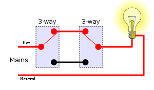
Multiway Switching Wikipedia from upload.wikimedia.org 3 way light switching (new cable colours) 3 way light switch (old cable colours) 3 way light switch using a two wire control; Notes on wiring reduce unwanted electrical noise by using shielded coaxial cable for your longer wiring runs (for example, the connection between the controls and the output jack). The power source is coming to light fitting first. 2 brass terminals for the 2 traveler wires, and 1 common (black) terminal for the common wire. Below is the schematic diagram of the wiring for connecting a dpdt toggle switch: The ground wire is pigtailed with a wire connector at the switch boxes and the ceiling box. Nov 23, 2017 · two way switch can be operated from any of the switch independently, means whatever be the position of other switch(on/off), you can control the light with other switch. Terminals 3 and 4 represent the toggle switch.
Terminals 3 and 4 represent the toggle switch.
The power source is coming to a light switch first. We will now go over the wiring diagram of a dpdt toggle switch. The ground wire is pigtailed with a wire connector at the switch boxes and the ceiling box. Notes on wiring reduce unwanted electrical noise by using shielded coaxial cable for your longer wiring runs (for example, the connection between the controls and the output jack). The power source is coming to light fitting first. A dpdt toggle switch has 6 terminals. 2 way switch (3 wire system, old cable colours) 2 way switch (two wire control) three way switching. 2 brass terminals for the 2 traveler wires, and 1 common (black) terminal for the common wire. While the physical location of the 4 way switch may be anywhere, the electrical location of the switch is always between the two 3 way switches. Below is the schematic diagram of the wiring for connecting a dpdt toggle switch: These terminals receive the power necessary to drive the loads on. 3 way light switching (new cable colours) 3 way light switch (old cable colours) 3 way light switch using a two wire control; Nov 23, 2017 · two way switch can be operated from any of the switch independently, means whatever be the position of other switch(on/off), you can control the light with other switch.
We will now go over the wiring diagram of a dpdt toggle switch 3 way switch wiring. 2 way switch (3 wire system, old cable colours) 2 way switch (two wire control) three way switching.


0 Komentar